
PIC Microcontroller Series — Part 3
PIC Microcontroller Series - 3
Adding user input: button-controlled LEDs. Learn digital input, external pull-ups, pin configuration for mixed I/O, debouncing, and simple state-machine design.
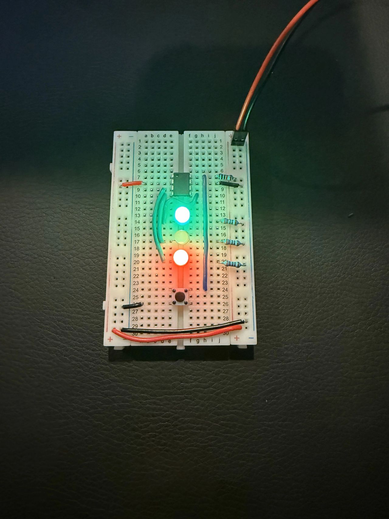
Adding User Input: Button-Controlled LEDs
From blink to interactive control
In Part 2, we mastered the fundamentals — making an LED blink with precise timing. But embedded systems aren't just about outputs; they need to respond to the real world. Today, we're adding a button and two more LEDs to create our first interactive PIC program.
I have posted the code for this project on GitHub:
What you'll learn:
- Reading digital inputs (button sensing)
- Controlling multiple outputs simultaneously
- Debouncing techniques for reliable input
- Pin configuration for mixed I/O applications
Hardware setup: three LEDs and a button
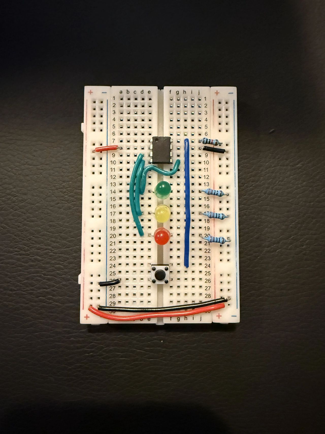
We're upgrading from one LED to a complete I/O system.
Pin assignment:
GP0(Pin 5) → Green LED (with 220 Ω resistor to ground)GP1(Pin 4) → Yellow LED (with 220 Ω resistor to ground)GP2(Pin 3) → Red LED (with 220 Ω resistor to ground)GP3(Pin 8) → Button input (active-low with 10 kΩ pull-up to +5V)
The button circuit
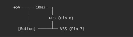
Why this works:
- Button released:
GP3pulled high (+5V) by resistor = logic1 - Button pressed:
GP3connected to ground = logic0 - Active-low logic: We read
0when the button is pressed
Pull-up resistor selection guide
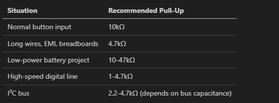
Choosing the right pull-up resistor value depends on your application.
Why 10 kΩ for our project:
- Strong enough to ensure reliable HIGH logic level
- Weak enough to minimize current draw (0.5 mA when button pressed)
- Standard value that works well for breadboard prototyping
Code analysis: from single to multiple I/O
Let's examine how our code evolved from the simple blink program.
Pin configuration

Breaking down the TRIS value:
- Bit 3 (
GP3) =1→ Input for button - Bit 2 (
GP2) =0→ Output for red LED - Bit 1 (
GP1) =0→ Output for yellow LED - Bit 0 (
GP0) =0→ Output for green LED
This gives us one input and three outputs — exactly what we need.
OPTION register: disabling pull-ups

Key change from Part 2:
GPPU = 1→ Disables internal weak pull-ups- Why: We're using our own external 10 kΩ pull-up resistor
The external pull-up is stronger and more predictable than the internal weak pull-ups (~20-50 kΩ), giving us cleaner digital signals.
New instruction: clrf — clear file register

Before we start our main loop, we initialize all GPIO pins to a known state.
What clrf does:
- Operation: Sets all bits in the specified register to
0 - Effect on GPIO: All output pins go LOW
- Result: All LEDs start in the OFF state
Why initialize GPIO?
- The problem: When the PIC powers up, GPIO register contents are undefined. Your LEDs might randomly be on or off!
- The solution:

clrf vs. multiple bcf instructions
You could achieve the same result with:

But clrf is:
- Faster: 1 instruction vs. 3 instructions
- Cleaner: Single operation, easier to read
- Complete: Clears ALL bits, including unused ones
When to use each:
clrf— When you want to clear an entire registerbcf— When you want to clear specific bits only
Debouncing: dealing with mechanical switches
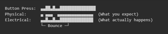
Real buttons aren't perfect — they "bounce" when pressed, creating multiple rapid on/off transitions that can confuse your program.
The problem:
Our solution: 20 ms debounce delay
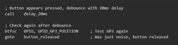
The strategy:
- First detection: Button appears pressed
- Wait 20 ms: Let mechanical bouncing settle
- Re-test: Check if button is still pressed
- Confirm: If still low, button is genuinely pressed
Why 20 ms? Most mechanical switches settle within 10-20 ms. This gives us reliable detection without noticeable delay to the user.
LED control logic: state-based design
Our program implements two distinct states.
State 1: Normal operation (button released)
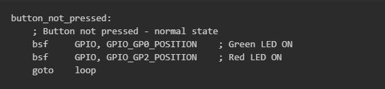
Result: Green + Red LEDs ON, Yellow LED OFF.
State 2: Button active (button pressed)
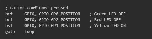
Result: Yellow LED ON, Green + Red LEDs OFF.
State 3: Button released detection
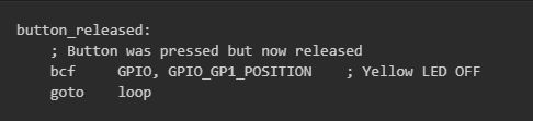
Result: All LEDs OFF momentarily, then returns to normal state. Remember that the Green and Red LEDs were already OFF, so we only need to turn the Yellow LED OFF here.
Program flow: state-machine design
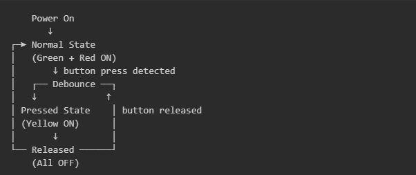
Our button program is actually a simple state machine.
Benefits of this design:
- Predictable: Each state has defined behavior
- Debuggable: Easy to trace program flow
- Expandable: Simple to add new states/buttons
- Reliable: Debouncing prevents false triggering
Key concepts mastered
1. Mixed I/O configuration
- Combining inputs and outputs on the same port
- External pull-up resistors for reliable input
- Active-low button logic
2. Bit-testing instructions
btfscfor conditional program flow- Skip-based branching logic
- Reading individual GPIO bits
3. Debouncing techniques
- Why mechanical switches bounce
- Software debouncing with time delays
- Confirming input stability
4. Multiple output control
- Simultaneous LED control
- Bit manipulation vs. register clearing
- State-based LED patterns
Your hard work in action
Normal state:
- Green — ON
- Yellow — OFF
- Red — ON
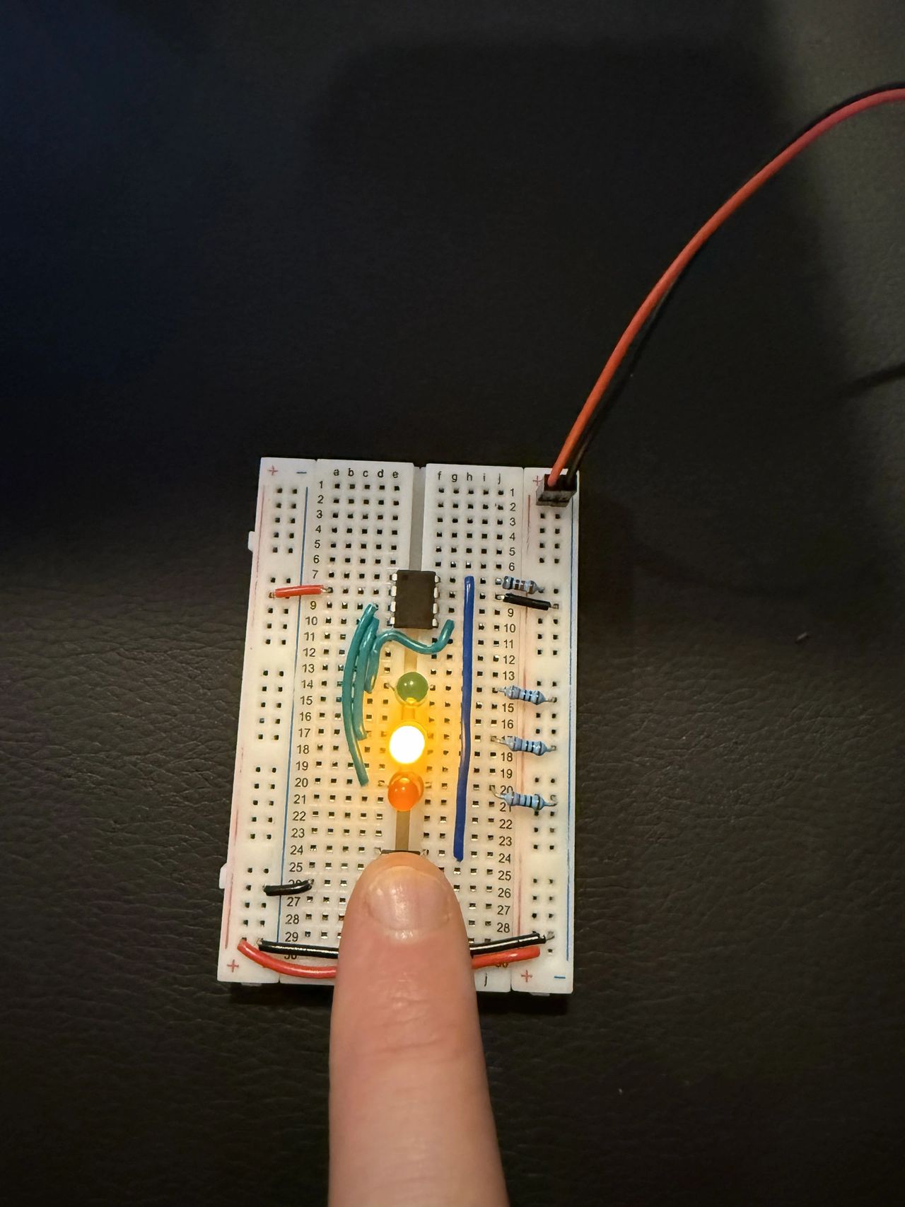
Button-pressed state:
- Green — OFF
- Yellow — ON
- Red — OFF
What's next: Part 4 preview
In Part 4, we'll build a game or two from this simple button and 3-LED setup.
Comments
Comments are powered by Giscus + GitHub Discussions. Enable them by filling in siteConfig.comments in src/lib/config.ts.