
PIC Microcontroller Series — Part 4
PIC Microcontroller Series - 4
From interaction to games. Build a reaction timer and an LED sweeper using state machines, precision timing, and the STATUS register's Z and C flags.
From Interaction to Games: Building Fun with Embedded Systems
Taking control to the next level
In Part 3, we built our first interactive PIC system with three LEDs and a button. We learned about input/output configuration, debouncing, and bit testing. Now it's time to have some fun! Today we'll transform that simple button-and-LED setup into two engaging games that showcase real-world embedded programming concepts.
What you'll learn:
- State-machine programming for complex behavior
- Precision timing for game mechanics
- Advanced button handling and event detection
- LED pattern generation and control
- Game logic implementation in assembly
Hardware setup: same circuit, new possibilities
We're using the exact same hardware from Part 3 — proof that creative software can transform simple circuits into engaging experiences.
Pin assignment (unchanged from Part 3):
GP0(Pin 5) → Green LED (with 220 Ω resistor to ground)GP1(Pin 4) → Yellow LED (with 220 Ω resistor to ground)GP2(Pin 3) → Red LED (with 220 Ω resistor to ground)GP3(Pin 8) → Button input (active-low with 10 kΩ pull-up to +5V)
Same circuit, different behavior
The beauty of embedded programming is that the same hardware can create entirely different experiences through software. Our three LEDs will become:
- Game indicators (ready, go, win, lose)
- Timing displays (fast, medium, slow reactions)
- Animation sequences (sweeping patterns, celebrations)
Game 1: Reaction Timer — test your reflexes
Our first game tests how quickly you can react to a visual cue. It's a classic embedded programming exercise that demonstrates timing, state machines, and user feedback.
GitHub code: PIC10F200/asm/reaction.s at main · RavenMicroLab/PIC10F200
How the game works
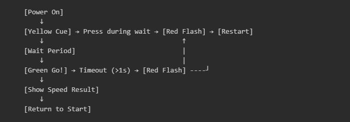
- Setup phase: Yellow LED cues you to get ready
- Wait phase: Random delay prevents cheating
- Go phase: Green LED appears — react as fast as possible!
- Result phase: Feedback shows your reaction speed
- Green: Fast reaction (< 300 ms)
- Yellow: Medium reaction (300-600 ms)
- Red: Slow reaction (> 600 ms)
State-machine design
Key programming techniques
1. False-start detection:
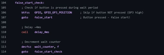
2. Precision reaction timing:
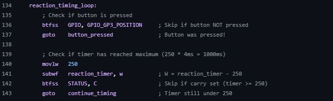
3. Speed classification: the game measures reaction time in 4 ms increments:
- Fast: < 75 counts (< 300 ms)
- Medium: 75-150 counts (300-600 ms)
- Slow: > 150 counts (> 600 ms)
Educational value
This game teaches several embedded concepts:
- Real-time response: The system must detect button presses immediately
- Timing precision: 4 ms resolution provides meaningful measurements
- State management: Clear states prevent confusion and bugs
- User feedback: Visual indicators communicate system state
Game 2: LED Sweeper — timing and precision
The second game challenges your timing skills with a continuously moving LED pattern. Hit the button exactly when the green LED is active to advance levels and increase difficulty.
GitHub code: PIC10F200/asm/sweeper.s at main · RavenMicroLab/PIC10F200
How the game works
- Sweep animation: LEDs light in sequence: Green → Yellow → Red → Yellow → Green
- Timing challenge: Press the button only when green LED is active
- Level progression: Three successful hits advance to the next level
- Speed increase: Higher levels sweep faster, making timing harder
- Win condition: Complete three levels for a victory celebration
- Failure: Miss the green LED and restart from level 1
The sweep pattern

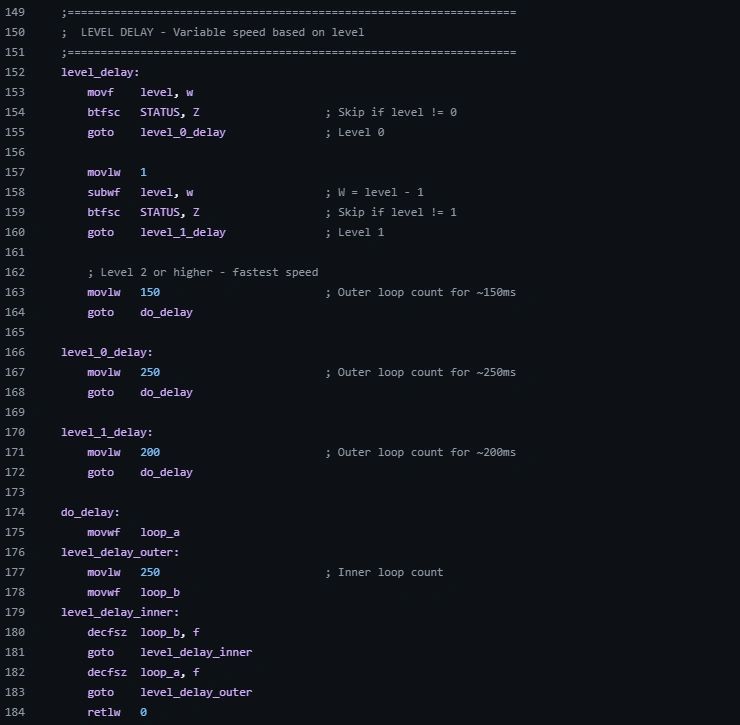
Level-based speed control
Advanced programming concepts
1. Sweep state machine:
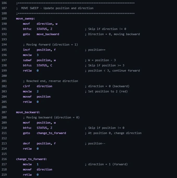
2. Level-progression logic:
- Track successful hits per level
- Increase speed (decrease delay) with each level
- Reset on any miss (hitting during non-green LED)
3. Win celebration:
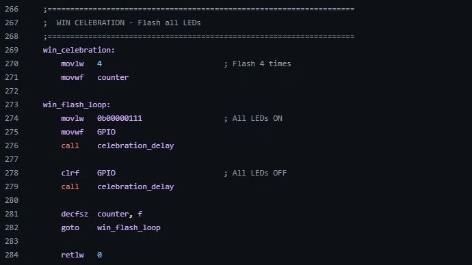
Game balance and difficulty curve
The sweeper game demonstrates important game-design principles:
- Progressive difficulty: Each level increases speed gradually
- Clear success/failure: Immediate feedback on button timing
- Skill-based progression: Success requires genuine timing improvement
- Satisfying win condition: Celebration reward for completing challenge
New instruction: STATUS register flags
I should point out that we have a new instruction that we have not talked about previously. We need to understand two important STATUS register flags that these games use for decision-making.
The STATUS register
The STATUS register is a special 8-bit register that stores information about the result of arithmetic and logic operations. Two bits are particularly important for our games:
Bit 2: Z (Zero flag)
- Set (Z = 1): The result of the last operation was zero
- Clear (Z = 0): The result of the last operation was non-zero
Bit 0: C (Carry flag)
- Set (C = 1): The result was ≥ 256 (addition) or ≥ 0 (subtraction)
- Clear (C = 0): The result was < 256 (addition) or < 0 (subtraction)
How we use these flags
Zero flag (Z) for equality testing:

Checking if we're at position 0 (Green LED).
Zero flag (Z) for specific value testing:

Checking if position equals 1.
Carry flag (C) for range testing:

Checking if position has reached the end (≥ 3).
Why this matters
These flags let us make complex decisions without multiple instructions:
- Before: Multiple comparisons and branches
- After: Single subtraction + flag test
The sweeper's direction logic:

This technique powers the smooth LED sweeping pattern.
Advanced programming techniques used
1. Multi-state button handling
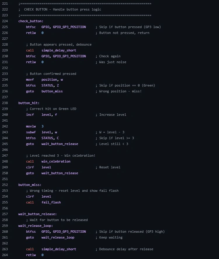
Unlike Part 3's simple pressed/not-pressed logic, these games need sophisticated button handling.
This prevents multiple triggers from a single button press — essential for game logic.
Comparing the games: design philosophy
Reaction Timer: simplicity and precision
- Goal: Measure and improve reaction speed
- Feedback: Immediate, quantified results
- Skill: Hand-eye coordination and reflexes
- Technical focus: Precise timing measurement
LED Sweeper: rhythm and anticipation
- Goal: Hit moving targets with perfect timing
- Feedback: Progressive difficulty and celebration
- Skill: Pattern recognition and rhythm
- Technical focus: Smooth animations and state machines
Both games demonstrate that embedded systems can be:
- Interactive: Responding to user input in real time
- Engaging: Creating compelling experiences through simple hardware
- Educational: Teaching timing, precision, and coordination
- Scalable: Adding features through software without hardware changes
Code analysis: key lessons
Lesson 1: State machines make complex behavior simple
Both games use clear state machines that make the code:
- Predictable: Each state has defined entry/exit conditions
- Debuggable: Easy to track what the system should be doing
- Expandable: New states can be added without breaking existing code
Lesson 2: Timing is everything in embedded systems
These games demonstrate three types of timing:
- Delays: Fixed waits for animations and debouncing
- Measurements: Capturing user reaction speed
- Rhythms: Creating smooth, repeatable patterns
Lesson 3: User experience through simple hardware
Great embedded applications focus on the experience, not the hardware complexity:
- Clear feedback: Users always know the system state
- Immediate response: Button presses are handled quickly
- Progressive challenge: Difficulty scales with user skill
- Satisfying completion: Win conditions feel rewarding
Expanding the games
Reaction Timer enhancements
- Add difficulty levels with shorter time windows
- Include multiple rounds with score tracking
- Create different speed categories
- Add sound effects using a buzzer
LED Sweeper improvements
- Reverse sweep directions randomly
- Add multiple sweep patterns
- Implement a lives system (3 misses = game over)
- Create tournament mode with high scores
Advanced features (requires more capable PICs)
Note: The PIC10F200 is a very basic microcontroller. These features require upgrading to more capable PICs like the PIC16F series.
- Hardware timers: precise timing without blocking delays (PIC16F1455+)
- Interrupts: instant response to events (PIC16F series)
- EEPROM: saving high scores and settings (PIC16F series)
- Serial communication: connecting multiple players (PIC16F series)
- PWM: LED brightness control for better visual effects (PIC16F series)
What's next: Part 5 preview
Time to level up: we've reached the practical limits of the PIC10F200. This basic microcontroller has no interrupts, no timers, and very limited memory.
In Part 5, we'll make a big leap by upgrading to the PIC16F1455 and building a retro gaming interface that reads an actual NES controller and controls LEDs through shift registers.
What we'll explore:
- NES controller protocol: Reading 8 buttons using serial communication
- Shift-register expansion: Controlling 8+ LEDs with only 3 pins
- Real-time input processing: Instant response to multiple button combinations
- Hardware timing: Using the PIC16F1455's enhanced capabilities
- Serial communication: Understanding shift-register protocols
The project: Connect an authentic NES controller to your PIC microcontroller and watch as each button press (A, B, Select, Start, D-pad) lights up a corresponding LED. This project bridges retro gaming and modern embedded systems, teaching essential concepts like:
- Serial data protocols
- Hardware expansion techniques
- Multi-input processing
- Real-time embedded applications
From simple LED games to reading classic gaming controllers — embedded programming keeps getting more exciting.
These games prove that embedded programming isn't just about controlling hardware — it's about creating experiences that engage and challenge users while teaching important technical concepts.
This is Part 4 of our PIC Microcontroller Series. Master these game programming concepts to understand how embedded systems create engaging user experiences.
Related project
Comments
Comments are powered by Giscus + GitHub Discussions. Enable them by filling in siteConfig.comments in src/lib/config.ts.