
PIC Microcontroller Series — Part 1
PIC Microcontroller Series - 1
Getting started with PIC microcontrollers using the PIC10F200: what you need, how to set up your dev environment, and your first blink program in assembly and C.
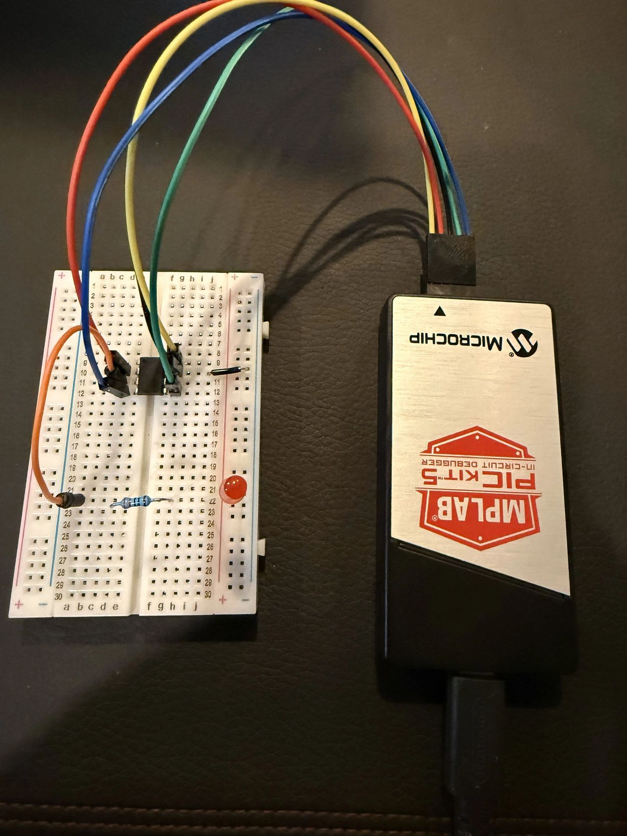
A Beginner-Friendly Introduction Using the PIC10F200
If you're curious about microcontrollers but don't know where to begin, the PIC10F200 is one of the simplest — and most charming — places to start. It's an 8-pin device with just enough features to teach the fundamentals without overwhelming you. Think of it as the "Hello, World" of the PIC ecosystem.
In this post we'll walk through:
- What you need to start programming PIC microcontrollers
- How to set up your development environment
- A simple LED blink program in assembly and C
- How each language affects program size on a tiny device like the PIC10F200
By the end, you'll have a working development setup and your first running program.
What you need to begin
PIC microcontrollers are extremely accessible, but you do need a few tools to get started.
1. A PIC microcontroller
We'll be using the PIC10F200, a baseline 8-bit PIC with:
- 256 words of program memory
- 16 bytes of RAM
- 4 GPIO pins
- Internal oscillator
- No peripherals (which is great for learning fundamentals)
2. A programmer
To load code onto the chip, you need a hardware programmer such as:
- PICkit 4 or 5
- MPLAB SNAP (budget option)
These connect to your computer via USB and to the PIC via the In-Circuit Serial Programming (ICSP) pins (VPP, VDD, GND, ICSPDAT, ICSPCLK).
3. MPLAB X IDE + XC compilers
Microchip's free development environment includes:
- MPLAB X IDE — project management, editing, debugging
- XC8 Compiler — for C programs
- pic-as — Microchip's modern assembly toolchain
Once installed, you can write, compile, and program your PIC all from one place.
4. A simple test circuit
To verify your setup, you only need:
- PIC10F200
- One LED
- One 220-1kΩ resistor
- Breadboard + jumper wires
- 5V power supply (or USB power module)
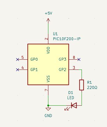
Connect the LED to GP2 through the resistor, and you're ready to blink.
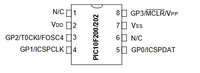
Once the chip has been programmed, you only need to supply power and a common ground. Then your electrical schematic would look like this:
Your first program: "Hello, World" for microcontrollers
In embedded systems, the classic "Hello, World" is a blinking LED. If the LED blinks, you know:
- Your programmer works
- Your IDE is configured
- Your PIC is alive
- Your code compiled correctly
- Your wiring is correct
It's the perfect sanity check before diving deeper.
Check out the GitHub links below to use my examples for assembly and C code. We'll cover what's actually going on in this code in future posts.
Assembly vs. C: program size comparison
One of the most interesting lessons on a tiny PIC like the 10F200 is how dramatically program size differs between languages.
Here's what beginners usually discover with this blink project:
- Assembly — Extremely compact; you control every instruction.
- C (XC8) — Easier to use with predefined functions like
__delay_ms(). C typically reserves space for variables, stack, and runtime housekeeping (even if unused), which adds to the RAM usage.
The PIC10F200 has a limit of 256 words total. You can fill it surprisingly fast in C.
This doesn't mean C is "bad" — just that on baseline PICs, you must be mindful of memory. On larger PICs (PIC16F, PIC18F), C is the dominant choice. But on the 10F200, assembly is still very practical.
What beginners learn from this exercise
This first blink program teaches several foundational concepts:
- ✔ How to configure GPIO — TRIS registers, input/output modes, and the quirks of
GP2andGP3. - ✔ How to use the OPTION register — prescalers, pull-ups, wake-up behavior.
- ✔ How to write and call delay loops — a classic embedded technique, especially on chips without timers.
- ✔ How reset vectors work — the PIC10F200's reset vector is at the end of memory, not the beginning.
- ✔ How assembly and C differ in size and structure — a valuable lesson for anyone working with resource-constrained devices.
Parts list
The PICkit programmer is the most expensive piece of this project, coming in at around $75. It's a one-time investment and it opens up a whole world of learning opportunities.
Here are the parts if you want to build this project yourself:
The MPLAB X Integrated Development Environment (IDE) is free from Microchip Technology. This application allows you to code, debug, and program (with the PICkit programmer) your microcontroller.
MPLAB® X IDE | Microchip Technology
Where we go next
Now that your toolchain is working and your PIC is blinking happily, the next steps could include:
- Review the PIC10F200 datasheet
- Understanding the PIC10F200 architecture
- GPIO deep dive (latching, read-modify-write behavior)
- Writing your own delay routines
- Using the watchdog timer
- Creating your first reusable library (in assembly or C)
Related projects
Regulator v2 — Switching 12 V → 5 V / 3.3 V
A switching redesign of the linear regulator: two Diodes Incorporated AP6320x buck converters drop 12 V to 5 V and 3.3 V at over 90 percent efficiency, with the same breadboard-friendly footprint and connectors as v1.
Regulator v1 — Linear 12 V → 5 V / 3.3 V
A simple four-layer breakout that drops a 12 V wall wart down to breadboard-friendly 5 V and 3.3 V rails using an LM7805 and a TPS79333 LDO. Meant as a first PCB and a permanent bench-side power brick.
Comments
Comments are powered by Giscus + GitHub Discussions. Enable them by filling in siteConfig.comments in src/lib/config.ts.