
Regulator v2 — Switching 12 V → 5 V / 3.3 V
A switching redesign of the linear regulator: two Diodes Incorporated AP6320x buck converters drop 12 V to 5 V and 3.3 V at over 90 percent efficiency, with the same breadboard-friendly footprint and connectors as v1.
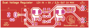
Board specs
- Input
- 12 V DC via 2.1 mm barrel jack
- Output
- 5 V @ 2 A (AP63205)
- 3.3 V @ 2 A (AP63203)
- Layers
- 4 layers
Overview
Regulator v2 is the switching-mode redesign of Regulator v1. It swaps the LM7805 + LDO stack for two Diodes Incorporated AP6320x synchronous buck converters — the AP63205 for the 5 V rail and the AP63203 for 3.3 V. Efficiency climbs from around 40% to over 90%, the board stays cool to the touch, and both rails can now source 2 A instead of 500 mA.
The mechanical envelope, terminal blocks, and DC jack all match v1 so the two boards are drop-in swappable in any bench setup.
Design intent
- Same shape, better power: identical mounting and connectors so it slots into any bench where v1 lived.
- AP6320x picked for beginner-friendliness: fixed-output-voltage variants, internal MOSFETs, no external compensation. All you provide is the input cap, output cap, and inductor.
- Low-EMI variant: the AP6320x parts spread the switching spectrum, which keeps radiated noise on the 3.3 V rail low enough for microcontroller supply duty.
- 4.7 µH Würth WE-LHMI inductors on both channels — shielded so magnetic coupling into nearby circuits is minimal.
Trade-offs vs v1
Switching converters add a little high-frequency ripple that v1's linear stack does not. For sensitive analog work (ADC references, op-amp front ends) you may still want v1. For anything digital or motor-driven, v2 is the clear win.
See the side-by-side comparison on the Regulator v1 page for the full trade-off table.
Status
This board is a working prototype. Gerbers have not been ordered yet — the current test bring-up is running on hand-populated bare KiCad-fab PCBs. Once the rails hold their voltage under a real load for 24 hours, I'll publish the fabrication package here.
Bringing it up
- Populate the input side only. Apply 12 V. Verify the AP63205's VIN pin sees 12 V and its SW pin is quiet.
- Populate the output stage of the 5 V channel. Verify 5.0 V ± 100 mV under no load, and under a 1 A dummy load.
- Repeat for the 3.3 V channel.
- Scope both rails at the terminal block with a 20 MHz bandwidth limit — ripple should be under 30 mV pk-pk.
Next revision (v3, planned)
- Add a USB-C input option alongside the barrel jack.
- Bring a shutdown pin out to a header for wake-on-external control.
- Drop the second-source AP63203 for a jellybean 3.3 V buck to make sourcing easier.
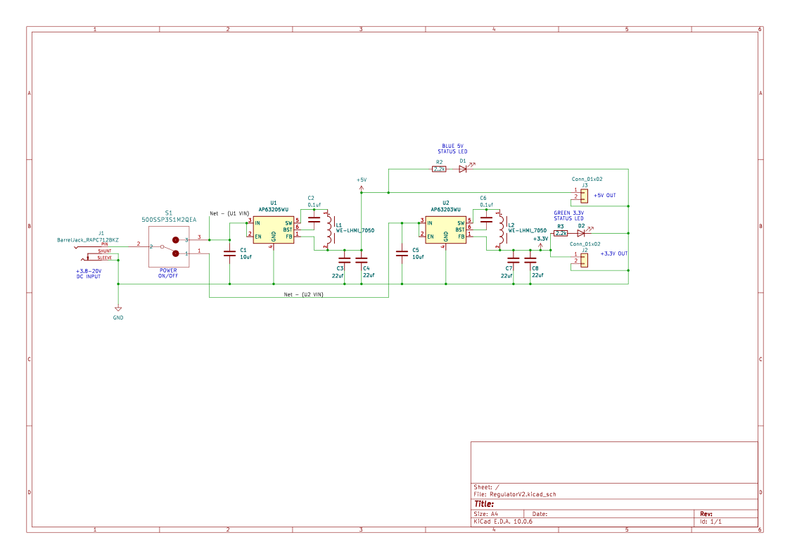
Schematic
Drag to pan · scroll to zoom
Top layer
Drag to pan · scroll to zoom
Bill of materials
14 line items · 23 total parts
| Ref | Qty | Value | Footprint | Manufacturer | MPN | Datasheet |
|---|---|---|---|---|---|---|
| C1,C5 | 2 | 10uF 25V X7R 1206 | Capacitor_SMD:C_1206_3216Metric | Yageo | CC1206KKX7R8BB106 | |
| C2,C3,C7,C8 | 4 | 22uF 10V X7R 1206 | Capacitor_SMD:C_1206_3216Metric | KEMET | C1206C226K8RAC | |
| C4,C6 | 2 | 0.1uF 25V X7R 0805 | Capacitor_SMD:C_0805_2012Metric | Murata | GRM21BR71E104KA01L | |
| D1 | 1 | BAT43 Schottky | Diode_SMD:D_SOD-123 | Vishay | BAT43W-HE3-08 | |
| D2 | 1 | LED Red 0805 | LED_SMD:LED_0805_2012Metric | Lite-On | LTST-C170KRKT | |
| D3 | 1 | LED Blue 0805 | LED_SMD:LED_0805_2012Metric | Lite-On | LTST-C170TBKT | |
| D4 | 1 | LED Green 0805 | LED_SMD:LED_0805_2012Metric | Lite-On | LTST-C170KGKT | |
| J1 | 1 | Barrel Jack | RavenMicroLab:SWITCHCRAFT_RAPC712BKZ | Switchcraft | RAPC712BKZ | |
| J2 | 1 | Terminal Block 2-pin | TerminalBlock_Phoenix:TerminalBlock_Phoenix_MPT-0,5-2-2.54_1x02_P2.54mm_Horizontal | Phoenix Contact | 1725656 | |
| L1,L2 | 2 | 4.7uH Inductor WE-LHMI 7050 | RavenMicroLab:Inductor_WE-LHMI_7050 | Würth Elektronik | 74437349047 | |
| R1,R2,R3 | 3 | 2.2k 0805 | Resistor_SMD:R_0805_2012Metric | Yageo | RC0805FR-072K2L | |
| S1,S2 | 2 | Slide Switch | RavenMicroLab:SW_Slide_THD_JS202011CQN | C&K | JS202011CQN | |
| U1 | 1 | AP63205WU 5V Buck | Package_TO_SOT_SMD:TSOT-23-6 | Diodes Inc. | AP63205WU-7 | |
| U2 | 1 | AP63203WU 3.3V Buck | Package_TO_SOT_SMD:TSOT-23-6 | Diodes Inc. | AP63203WU-7 |
Downloads
Everything you need to fabricate or remix this board.