
Regulator v1 — Linear 12 V → 5 V / 3.3 V
A simple four-layer breakout that drops a 12 V wall wart down to breadboard-friendly 5 V and 3.3 V rails using an LM7805 and a TPS79333 LDO. Meant as a first PCB and a permanent bench-side power brick.
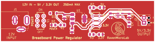
Board specs
- Input
- 12 V DC via 2.1 mm barrel jack
- Output
- 5 V @ 500 mA (LM7805)
- 3.3 V @ 200 mA (TPS79333 LDO)
- Layers
- 4 layers
Overview
Regulator v1 is the "always plugged in" power source for the breadboard-based PIC10F200 tutorials in Series 1 through Series 4. It takes 12 V from a wall wart and produces two clean rails — 5 V and 3.3 V — that you can jumper straight to a breadboard.
The design is deliberately old-school: a linear LM7805 for the 5 V rail and a TPS79333 LDO fed from the 5 V rail for 3.3 V. That's inefficient at the input voltage, but it's dead-quiet electrically and needs no inductor — perfect for the analog-noise-sensitive experiments in the microcontroller series.
Design intent
- First-PCB approachable: everything is through-hole except the LDO.
- Rock-solid rails: bulk caps on both input and output, plus 100 nF ceramics right at the regulator pins.
- Breadboard-friendly outputs: Phoenix Contact MPT terminal blocks at 3.5 mm pitch on each rail.
- Four-layer for a reason: internal ground and power planes cut noise and give the LM7805 a lot more copper to dump heat into.
Trade-offs vs Regulator v2
| v1 (this board) | v2 | |
|---|---|---|
| Topology | Linear (LM7805 + LDO) | Switching (AP63205 + AP63203 bucks) |
| Efficiency at 12 V in / 5 V out | ~40% | >90% |
| Output ripple | Very low | Low but not zero |
| BOM cost | Lowest | Slightly higher |
| Heat dissipation | Regulator gets warm | Cool to the touch |
Choose v1 when you need dead-quiet rails for analog work. Choose v2 when you're running the board off a battery or you want to leave it plugged in 24/7 without heating the room.
Bringing it up
- Confirm the input jack polarity with a meter before applying power.
- Power up with no load and verify both rails read within 2% of nominal.
- Load-test the 5 V rail with a 10 Ω resistor for a few seconds and re-check — the LM7805 will get warm; it should not get hot.
- Repeat the load test on the 3.3 V rail with 22 Ω.
Manufacturing notes
Four-layer board, standard KiCad Gerbers, 1.6 mm FR-4. The default 1 oz copper is fine for the 500 mA continuous rating; go 2 oz if you plan to run near the LM7805's thermal limit.
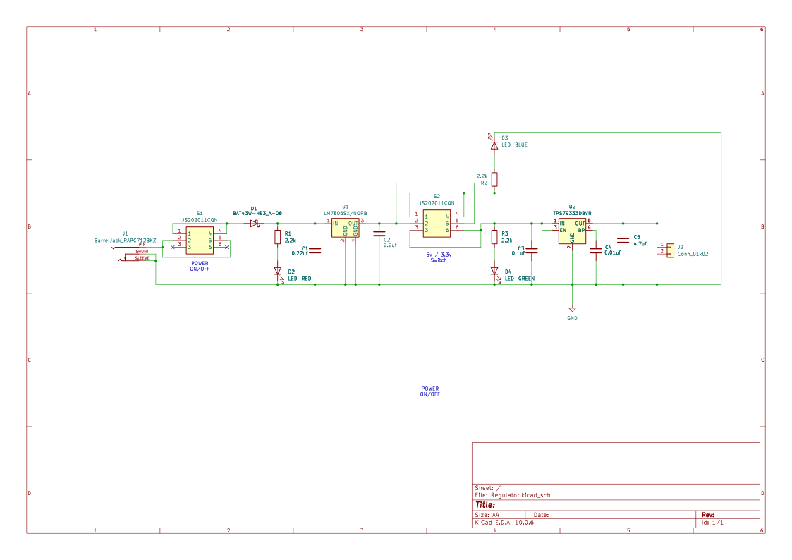
Schematic
Drag to pan · scroll to zoom
Top layer
Drag to pan · scroll to zoom
Bill of materials
14 line items · 14 total parts
| Ref | Qty | Value | Footprint | Manufacturer | MPN | Datasheet |
|---|---|---|---|---|---|---|
| C1 | 1 | 0.22uF | Capacitor_SMD:C_0805_2012Metric | Murata | GRM21BR71E224KA01L | |
| C2 | 1 | 2.2uF | Capacitor_SMD:C_0805_2012Metric | Yageo | CC0805KKX7R8BB225 | |
| C3 | 1 | 0.1uF | Capacitor_SMD:C_0805_2012Metric | Kemet | C0805C104K5RACTU | |
| C4 | 1 | 0.01uF | Capacitor_SMD:C_0805_2012Metric | Murata | GRM216R71E103KA01L | |
| C5 | 1 | 4.7uF | Capacitor_SMD:C_0805_2012Metric | Murata | GRM21BR71A475KE51L | |
| D1 | 1 | BAT43W-HE3 | Diode_SMD:D_SOD-123 | Vishay | BAT43W-HE3-08 | |
| D2 | 1 | LED-RED | LED_SMD:LED_0805_2012Metric | Lite-On | LTST-C170KRKT | |
| J1 | 1 | BarrelJack_RAPC712BKZ | RavenMicroLab:SWITCHCRAFT_RAPC712BKZ | Switchcraft | RAPC712BKZ | |
| J2 | 1 | Conn_01x02 | TerminalBlock_Phoenix:TerminalBlock_Phoenix_MPT-0,5-2-2.54_1x02_P2.54mm_Horizontal | Phoenix Contact | 1725656 | |
| J3 | 1 | Conn_01x02 | TerminalBlock_Phoenix:TerminalBlock_Phoenix_MPT-0,5-2-2.54_1x02_P2.54mm_Horizontal | Phoenix Contact | 1725656 | |
| R1 | 1 | 2.2k | Resistor_SMD:R_0805_2012Metric | Yageo | RC0805FR-072K2L | |
| S1 | 1 | JS202011CQN | RavenMicroLab:SW_Slide_THD_JS202011CQN | C&K | JS202011CQN | |
| U1 | 1 | LM7805SX/NOPB | Package_TO_SOT_SMD:SOT-223 | Texas Instruments | LM7805SX/NOPB | |
| U2 | 1 | TPS79333DBVR | Package_TO_SOT_SMD:SOT-23-5 | Texas Instruments | TPS79333DBVR |
Downloads
Everything you need to fabricate or remix this board.